V-Groove PCB Depaneling for LED Manufacturing: Cut Costs and Boost Output
By eliminating the physical bending that cracks ceramic LED chips and MLCCs, you can boost your final yield by up to 5% and virtually eliminate field failures.
If you’re looking for the bottom line on LED assembly, here it is: Switching from traditional mechanical V-cut splitting to high-precision, low-stress singulation is the fastest way to slash your defect rates and protect your margins. By eliminating the physical bending that cracks ceramic LED chips and MLCCs, you can boost your final yield by up to 5% and virtually eliminate field failures.
At PCBSEP, we’ve spent years on the factory floor helping engineers move away from “pizza cutters” and manual snapping toward automated, stress-free solutions. We know that in the LED world, output is king, but reliability is what keeps your customers coming back.
1. What Is V-Groove PCB Depaneling?
V-groove depaneling, or V-scoring, is a method where a “V” shaped channel is cut into both sides of a PCB panel, leaving a thin bridge of material (the residual web) to hold the boards together during SMT assembly. The “depaneling” part happens at the end of the line when you separate these individual boards.
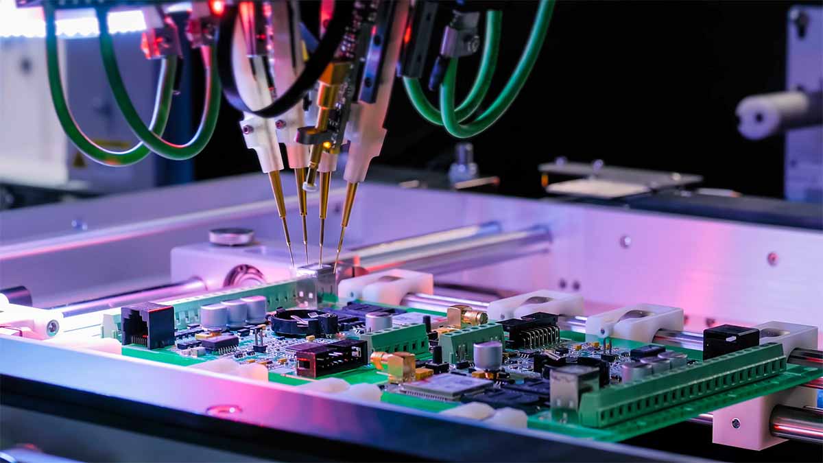
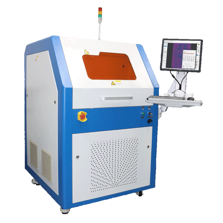
Traditionally, this meant using a blade to shear through that web. However, in modern high-end manufacturing, we often replace that mechanical blade with a pcb laser depaneling machine to ensure there is zero physical contact. The goal is to move from a process that “snaps” the board to one that “releases” it cleanly.
2. Why Choose V-Groove Depaneling for LED Manufacturing?
For LED manufacturers, V-groove panelization is usually the go-to because it allows for very high panel density. Unlike tab-routing, which requires wider gaps between boards, V-grooves let you line up LED strips side-by-side with almost zero wasted space.
Higher Throughput: You can process hundreds of LEDs on a single large panel.
Lower Material Waste: Less “real estate” is spent on rails and tabs.
Cost Efficiency: For long, rectangular LED light bars, it’s the most economical way to design a panel.
But there’s a catch. LEDs—especially those with ceramic substrates—are incredibly brittle. According to technical documentation from Cree LED (Avoidance of Ceramic-Substrate-Based LED Chip Cracking), mechanical flexure during the splitting of V-grooves is a leading cause of latent failures. This is why we advocate for pcb singulation methods that prioritize zero mechanical stress.
Best Practice: If you are running high-power LEDs, always perform a strain gauge test on your V-groove splitting process. If your strain exceeds 500 microstrain, you are likely micro-cracking your components.
3. How the V-Groove PCB Depaneling Process Works
The process starts at the fabrication house where they score the V-shape into your FR-4 or Aluminum substrate. After your components are placed and reflowed, you have to separate them.
Alignment: The panel is placed in a fixture or on a conveyor.
Sensing: Automated systems use CCD cameras to find the exact center of the V-groove.
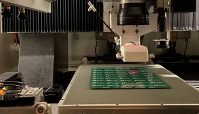
Separation: A blade or laser follows the path. When using our uv laser pcb depaneling machine, the laser vaporizes the residual web without touching the surrounding components.
Comparison: Mechanical vs. Laser Separation
Feature
Mechanical V-Cut Splitter
Laser Depaneling
Stress Level
High (Bending/Shearing)
Zero (Non-contact)
Edge Finish
Rough/Burred
Clean/Carbon-free
Component Safety
Risks of cracking
No risk
Flexibility
Straight lines only
Any shape/Contour
4. Key PCB Design Rules for Reliable V-Groove Separation
You can’t just “wing it” with V-grooves. If your design is off, your yields will tank. We recommend following IPC-2221 standards for board design, but for LED-specific high-yield runs, keep these our “in-house” rules in mind:
Residual Web Thickness: Usually 1/3 of the total board thickness. For a 1.6mm board, the web should be about 0.5mm.
Component Clearance: Keep sensitive components (LEDs, capacitors) at least 2.0mm to 3.0mm away from the V-score line if using mechanical tools. If using an inline pcb laser cutting system, you can reduce this to 0.1mm.
Vertical Alignment: The top and bottom V-scores must be perfectly aligned within ±0.05mm to prevent “stair-stepping” on the board edge.
Best Practice: For aluminum-core boards (IMS), ensure your V-groove angle is 30 degrees rather than the standard 45. This reduces the force required to separate the metal and minimizes burrs.
5. How to Choose the Right V-Groove PCB Depaneling Machine
Choosing a machine isn’t just about price; it’s about the “Total Cost of Ownership.” If a cheap machine causes a 2% failure rate on a $1,000,000 production run, that “savings” just cost you $20,000.
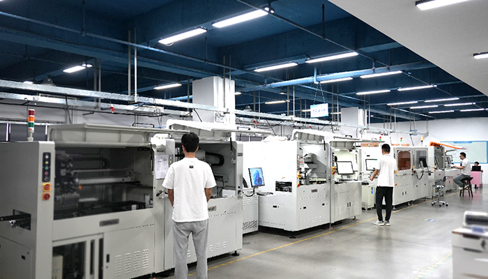
Volume: If you’re doing 24/7 mass production, you need an inline system with SMEMA compatibility.
Material: Are you cutting FR-4 or Aluminum? Aluminum requires more power and better thermal management, often found in specialized ims laser depaneling systems.
Precision: Look for machines with granite bases and linear motors. Any vibration during the cut will lead to uneven edges.
6. Common V-Groove Depaneling Problems and How to Fix Them
Even with the best design, things can go wrong. Here is what we see most often:
Problem: Component Cracking (MLCC/LED).
Cause: Excessive board flex during separation.
Fix: Move to a non-contact laser process or a multi-pass circular blade system that reduces the downward pressure.
Problem: Edge Burrs.
Cause: Dull blades or incorrect V-groove depth.
Fix: Implement a strict blade maintenance schedule or switch to a fpc laser cutting machine approach for flexible/thin boards where burrs are most common.
Problem: Solder Mask Chipping.
Cause: The mechanical blade “yanks” on the resin.
Fix: Adjust the blade speed or use a laser to “pre-cut” the mask layer.
7. V-Groove Blades, Cutting Quality, and Maintenance
If you stick with mechanical splitting, your blades are your biggest headache. A dull blade doesn’t cut; it crushes.
Blade Material: Use tungsten steel or diamond-coated blades for longer life.
Inspection: Operators should check for chips in the blade every 1,000 cuts.
The “Laser Advantage”: One reason many of our customers switch to laser is that there is no tool wear. A laser beam doesn’t get “dull.” Your 10,000th cut is exactly the same as your 1st.
8. Best Practices for High-Speed, Low-Cost PCB Depaneling
To get the most out of your line, we suggest a “Continuous Improvement” mindset:
Standardize Panel Sizes: This reduces the time spent adjusting machine rails.
Use Vacuum Fixturing: This holds the board perfectly flat, ensuring the laser or blade hits the V-groove at the perfect focal point.
Real-Time Monitoring: Use systems that log every cut and provide data to your MES.
Best Practice: When processing long LED strips, use a “bridge” support in the middle of the panel to prevent sagging during the reflow oven process, which can warp your V-grooves.
9. How to Automate V-Groove PCB Depaneling
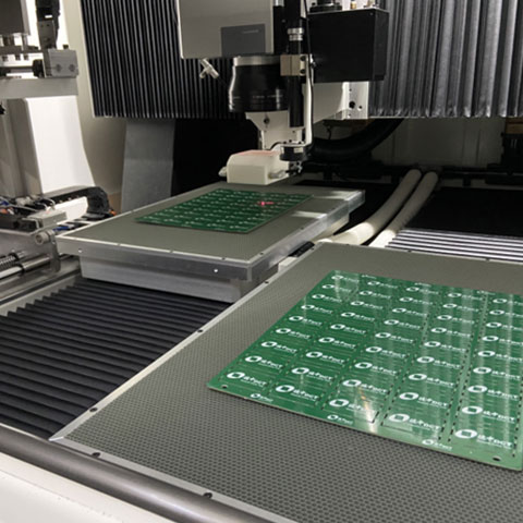
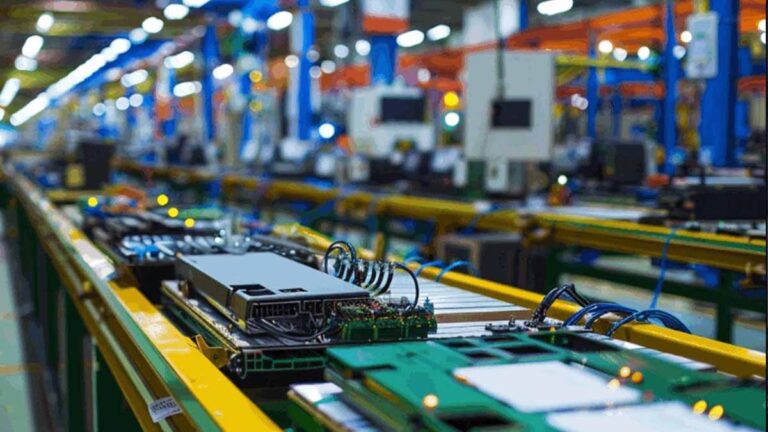
Automation is the only way to stay competitive. In a typical inline pcb laser cutting setup, the process looks like this:
The panel arrives via conveyor.
A robot or “pick-and-place” arm secures the panel.
The laser depathels the boards.
Individual boards are placed directly into shipping trays or the next assembly station.
This removes human error and reduces the risk of ESD (Electrostatic Discharge) from manual handling.
10. When V-Groove Is Not the Right Choice
As much as we love V-grooves, they aren’t perfect for every job. You should avoid V-grooves if:
You have complex, curved shapes. V-grooves only work in straight lines.
You have ultra-thin boards (<0.4mm). These are too fragile to score and snap.
You have “tall” components near the edge. Blades need clearance; if your component is too tall, the blade housing will hit it.
Cree LED Engineering: Avoidance of Ceramic-Substrate-Based LED Chip Cracking Induced by PCB Bending or Flexing. https://www.cree-led.com/media/documents/Avoidance-of-Ceramic-Substrate-Based-LED-Chip-Cracking-Induced-by-PCB-Bending-or-Flexing.pdf
IPC Standards: IPC-A-610 – Acceptability of Electronic Assemblies. https://www.ipc.org/ipc-standard-610
IPC Design Guidance: IPC-2221 – Generic Standard on Printed Board Design. https://www.ipc.org/TOC/IPC-2221B.pdf
Can I use V-groove for flexible PCBs (FPC)?
Generally, no. FPCs are too soft and will stretch rather than snap. For these, a fpc laser cutting machine is the industry standard.
Does laser depaneling burn the edges of the PCB?
Not if you use the right wavelength. Our UV lasers use “cold ablation,” which breaks molecular bonds rather than just burning through with heat. This leaves a clean, carbon-free edge.
What is the maintenance like for a laser system?
It’s much lower than mechanical systems. You don’t have blades to sharpen or bearings to grease daily. You mostly just need to keep the optics clean and check the filter in your dust extractor.
Is laser depaneling slower than a mechanical splitter?
On a pure “inches per second” basis, a blade is fast. However, when you factor in the time for blade changes, cleaning up dust, and the lack of board damage, laser systems often have a higher “effective” throughput.
How do I know if my LEDs are cracking from the V-cut?
You’ll usually see it as an “intermittent” failure. The LED might work at room temperature but fail when it heats up and expands. We suggest using a cross-section dye penetrant test to find these hidden micro-cracks.
Envíe su CAD y los detalles del panel; proporcionamos muestras de corte, fotografías, micrografías de bordes opcionales, parámetros láser recomendados y una estimación del tiempo de ciclo/rendimiento para que pueda decidir rápidamente.
Soporte de video remoto
Sesiones de video en vivo y encriptadas para configuración, ajuste de recetas, alineación de visión y mantenimiento básico. Programación rápida, listas de verificación claras y notas de seguimiento para mantener su línea en funcionamiento.
Puesta en marcha y capacitación en el sitio
Ingenieros certificados se encargan de la instalación, la calibración y la capacitación de los operadores, entregando los procedimientos operativos estándar (POE) y los resultados de aceptación según su estándar de calidad. Disponible en todas nuestras regiones de servicio.